Wall 1B Interruptions
In this retrofit wall assembly, the water control layer is in a familiar position relative to the sheathing of the wall but at an unfamiliar position relative to the rain shedding or cladding layer. All of the flashing details must connect to the water control layer at the wall sheathing and behind the insulating sheathing. As this water control layer is also the air control layer, particular attention is needed to maintain the airflow control through flashings.
Wall 1B Porch and Deck Connections

Porch Roof/Ceiling Connection to Wall 1B
- Curb of insulating sheathing is provided to allow access to step flashing during re- roofing of porch roof at a future date.

Deck Connection in Field of Wall 1B
- Curb of insulating sheathing is provided to allow access to the deck structure for future maintenance.

Deck Connection to Base of Wall 1B
- Curb of insulating sheathing is provided to allow access to the deck structure for future maintenance.
Wall 1B Windows and Doors
There are two kinds of windows-windows that leak, windows that will leak. This can be said of doors as well. Because of this, it is necessary to flash the window or door opening such that it is a drained opening - when the window or door leaks, water is controlled and the wall system is protected. Sill pan flashing, jamb flashing and head flashing form the water control system for the opening. The sill pan flashing is especially tricky because it must conform to the three dimensional corner configuration at the intersection of the sill and jamb of the opening. Also window and door frames tend to have sharp corners - if the sill pan flashing is not tight to the corner of the opening, the window or door frame could cause a tear in the flashing precisely at the most vulnerable location of the opening. For this reason, one should not attempt to provide pan flashing with flat peel-and-stick membranes. The corners of the sill pan flashing should be executed with pre-manufactured corner flashing, liquid-applied flashing membrane, or flexible flashing membrane.
When existing windows are retained, there may be a compromise to the water management of the wall. Even today (sadly) it is not common practice to install pan flashing in window openings. Older wood windows typically incorporate a continuous wood sill that is sloped to the outside and includes a drip reglet on the underside of the front edge. If properly maintained, such a wood sill may serve to direct water that leaks into the window (e.g. under or around window sash) back to the exterior. Where an existing window is retained within a wall to be retrofitted with insulating sheathing and new cladding, the details around the window should facilitate a minimally disruptive replacement of the window at some point in the future.

Flanged Window in Wall 1B-Head
- The pre-assembled trim extension box is described in Flanged Window in Wall 1B Trim Installation Sequence.
- Also see Flanged Window in Wall 1B - Installation Sequence.

Flanged Window in Wall 1B-Sill
- The pre-assembled trim extension box is described in Flanged Window in Wall 1B Trim Installation Sequence
- Also see Flanged Window in Wall 1B - Installation Sequence.

Flanged Window in Wall 1B-Jamb
- The pre-assembled trim extension box is described in Flanged Window in Wall 1B Trim Installation Sequence.
- Also see Flanged Window in Wall 1B - Installation Sequence.
Flanged Window in Wall 1B-Installation Sequence:


Flanged Window in Wall 1B-Trim Installation Sequence:


Existing Wood-Framed Window in Wall 1B-Head
- Replacement windows can be installed within the existing wood window frame with- out disturbing the cladding, exterior window trim, or trim extension.
- It is recommended that the trim extension be made of a non-water sensitive material.

Existing Wood-Framed Window in Wall 1B-Sill
- Replacement windows can be installed within the existing wood window frame without disturbing the cladding, exterior window trim, or trim extension.
- To facilitate removal, the cladding piece below the sill extension should terminate beneath the exterior jamb trim to either side of the window. Alternatively, a removable apron trim piece may be used.

Existing Wood-Framed Window in Wall 1B-Jamb
- Replacement windows can be installed within the existing wood window frame without disturbing the cladding, exterior window trim or trim extension.
- It is recommended that the trim extension be made of a non-water sensitive material.

Exterior Door in Wall 1B-Head
- The pre-assembled trim extension box is described in Exterior Door in Wall 1B Trim Installation Sequence.
- Also see Exterior Door in Wall 1B - Installation Sequence.

Exterior Door in Wall 1B-Sill
- Also see Exterior Door in Wall 1B - Installation Sequence.

Exterior Door in Wall 1B-Jamb
- The pre-assembled trim extension box is described in Exterior Door in Wall 1B Trim Installation Sequence.
- Also see Exterior Door in Wall 1B - Installation Sequence.
Exterior Door in Wall 1B-Installation Sequence:


Exterior Door in Wall 1B-Trim Installation Sequence:


Wall 1B Wire & Duct/Pipe Penetrations
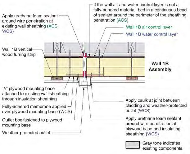

Exterior Electric Box Through Wall 1B-Plan and Section
- Vertical furring strips may be provided as needed for attaching ends of cladding at electric box; leave space for drainage between the box and any added furring strips.


Trim Block with Wire Penetration Through Wall 1B-Plan and Section
- This is for attachment of exterior lighting fixtures or other exterior electrical devices to be installed over a trim block.


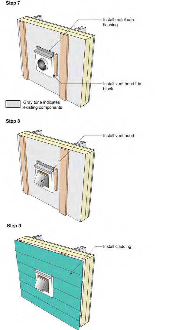
Duct/Pipe Penetration Through Wall 1B-Plan and Section
- Also see Duct/Pipe Penetration Through Wall 1B - Installation Sequence.
Duct/Pipe Penetration Through Wall 1B-Installation Sequence: